C.D.S. Newsletter October 2012
In this issue...
- TRACE 700 Version 6.2.9 Available
- TOPSS Update Includes New Version Control Process
- Frequently Asked Support Question
- Meet the C.D.S. Support Staff ... Eric Bleckinger and Charlie Jelen
TRACE 700™ Version 6.2.9 Now Available
Download update
TRACE 700, Load Design, Load Express, and Chiller Plant Analyzer updates are now available. The articles below detail the newest features in version 6.2.9. View the complete list of changes.
- New ASHRAE 90.1–2010 Minimally Compliant Equipment Library
- Updated calculation for dry fluid coolers and evaporative fluid coolers
- Ability to measure overall chiller plant efficiency
TRACE 700 90.1-2010 Equipment Library
The latest update to TRACE 700 includes the ASHRAE Standard 90.1-2010 Minimally Compliant Equipment Library, which contains a collection of equipment and assemblies from the standard’s Table 6.8.1 and Appendix A. The library can be used to model heating and cooling plants and envelope assemblies for Energy Cost Budget analyses and LEED baseline buildings. LEED v4 (the upcoming version formerly known as LEED 2012) relies heavily upon 90.1-2010.
How are changes in the standard reflected in the TRACE Library?
Several major changes distinguish ASHRAE 90.1-2010’s Table 6.8.1 from its predecessor. Variable-refrigerant-flow (VRF) air conditioners and heat pumps have been added to the equipment list, and computer-room air conditioners have been broken out from other unitary equipment. More equipment categories include part-load requirements, and IEER has largely replaced IPLV for defining these requirements. Lastly, 90.1-2010 has simplified the efficiency requirements for water-chilling packages into two alternatives for compliance: Path A emphasizes full-load performance while Path B emphasizes part-load requirements. Each path has both a full-load and a part-load metric to meet.
The 90.1-2010 library in TRACE incorporates these changes and addresses some other issues as well. Air-cooled VRF air conditioners and heat pumps are included in the library; computer-room air conditioners (CRACs) are also included but will require additional adjustment by users for accurate modeling. Standard 90.1-2010 requires CRACs to meet a certain “sensible COP” (SCOP), defined as:

ASHRAE defines net sensible cooling capacity as equipment gross sensible capacity minus the fan heat dissipated to the space, and defines total power input as all consumed energy apart from re-heaters and humidifiers. Because these values (and thus the SCOP value) will vary from project to project, we elected to enter the required SCOP value as the unit’s COP and allow users to adjust the full-load rate to suit their application. Additional information about SCOP can be found in ANSI/ASHRAE Standard 127. ASHRAE Standard 90.1-2010 references Standard 127-2007. Note: Standard 127-2012 has replaced the term SCOP with Net Sensible Coefficient of Performance (NsenCOP).
Lastly, in order to comply with LEED Interpretation IC 90.1-2007-09, air-cooled heat pumps will now operate in heating mode down to 17°F with progressively declining capacity (see Figure 1 for the capacity curve that has been assigned to air-cooled heat pumps). The 90.1-2004 and -2007 libraries will also be updated to reflect this change, which will alter energy consumption for projects using those libraries’ heat pumps.
Figure 1
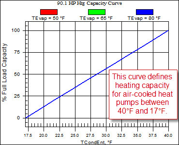
Within an average project, we expect that overall heat pump electric consumption will increase.
How was part-load efficiency integrated into the TRACE 90.1-2010 Library?
There is no direct input in TRACE 700 to enter the part-load efficiency values required by ASHRAE 90.1. Instead, part-load performance for a given piece of equipment is incorporated into the program using an unloading curve and an ambient relief curve. The unloading curve defines equipment power consumption based on load while the ambient relief curve modifies power consumption based on off-design condenser temperatures.
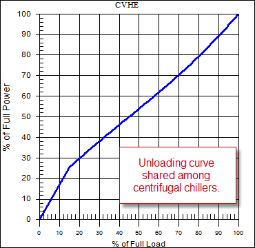
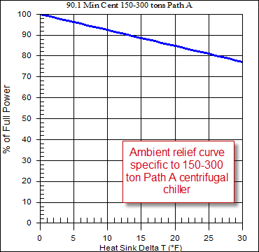
Each equipment category within the library uses a common unloading curve but accounts for different IEER or IPLV values using custom ambient relief curves. For instance, several centrifugal chillers contained in the library unload based on a CVHE curve (Figure 2), but each chiller uses its own individual ambient relief curve (Figure 3) to define its own part-load efficiency. This allows each family of equipment to unload in the same fashion while still accounting for consumption variances between different units.
Figure 2
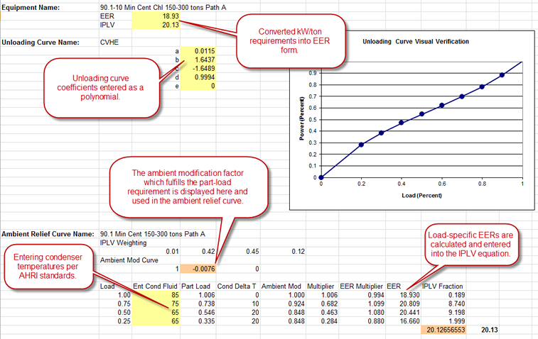
For each piece of equipment, efficiency values were calculated at 25%, 50%, 75%, and 100% load and entered into the IEER or IPLV equation (see the latest versions of ANSI/AHRI Standards 340/360 and 550/590 for more information on how IEER and IPLV are calculated). An ambient relief modifier was used to raise or lower these efficiency values based on entering condenser temperature, which allowed us to make part-load performance a function of ambient relief. The equipment minimum compliance with Standard 90.1 was established by using a combination of unloading and ambient relief curves. For each type of equipment, a representative unloading curve was selected from the existing unloading curves within the TRACE 700 curves library. Knowing the unloading curve data points, the full- and part-load requirements from Standard 90.1, and a single data point on the ambient relief curve, the ambient relief curve slope can be established. This data was then used to create the unloading and ambient relief curves for each piece of equipment. See Figure 4 for more details on the ambient-relief calculation:
Updated Fluid Cooler Calculations
The fluid cooler model in TRACE has been rewritten to accurately model fluid coolers as condenser-side heat rejection devices, as well as improve the simulation of free-cooling devices. New algorithms were implemented for dry fluid coolers and evaporative fluid coolers (aka closed-loop cooling towers), based on those used in EnergyPlus.
Both types of fluid coolers are still identified in the TRACE 700 Heat Rejection library in the Heat Rejection Type field. The value in the Makeup Water field determines the cooler type:
- For a dry fluid cooler model, the value in the Makeup Water field must be 0 gal/ton-hr. See screen example
- For an evaporative fluid cooler model, the value in the Makeup Water field must be greater than 0 or "To be calculated." See screen example
Measure Overall Chiller Plant Efficiency
A new kWh/Ton-hr metric has been added to the Economic Summary Report. This metric helps measure the overall efficiency of the cooling plant, as opposed to the efficiency of its individual components. The plant efficiency applies to water-cooled, air-cooled, unitary, or hybrid plant configurations.
TOPSS™ Update 8.8.050 Includes New Version Control Process
Download update
As part of a continuous effort to provide customers with the most current information, Trane has implemented a new version control process for TOPSS. TOPSS customers will be prompted to install a new version of the program every six months to ensure they are using the most current Trane product selections.
Installation Instructions [PDF]
Frequently Asked Question
How do you model an ice arena in TRACE 700?
When modeling an ice arena, you must take the following into account:
- The energy needed to freeze the skating surface and keep it frozen (using a chilled brine/water mixture piped underneath the surface).
- The cooling effect of the ice on the interior space.
- In some cases, the energy needed to keep the heated concrete base underneath the rink at a sufficiently high temperature to prevent the ground from freezing.
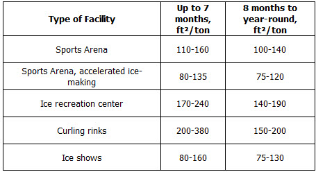
For a quick estimate of the chiller capacity needed to cool the chilled water/brine loop, refer to the table below from the 2006 ASHRAE Handbook—Refrigeration, Chapter 35. This chapter also contains a detailed breakdown of the load estimation procedure for a rink.
There are two different methods in TRACE to account for the heat lost by the space to the ice slab. In both cases, humidity control should be applied to the space to minimize the risk of dripping condensation on the ceiling or other surfaces of the rink.
Option 1
The first way involves calculating the heat gain manually and entering it as a miscellaneous load with a negative value. Convection and radiation gains to the ice should both be taken into account. The equations below are from the ASHRAE 2006 Handbook—Refrigeration.

Convection gain (including both sensible and latent heat gain) in Btu/h-ft²

where:
K = .17 lb/h-ft²
h = convective heat transfer coefficient = 0.6 + 0.00318V (V = velocity of air over the ice, ft/min)
ta= air temperature, °F
ti = ice temperature, °F
Xa= mole fraction of water vapor in air, (lb mol water)/(lb mol dry air) = 6.6 x 10^-3 at 38°F and 80% RH
Xi = mole fraction of water vapor in saturated ice, (lb mol water)/(lb mol ice) = 3.6 x 10^-3 at 21°F
Radiation gain in Btu/h-ft²:

where:
fci = gray body configuration factor, ceiling to ice surface; see Chapter 35, p. 3, of the handbook for details (values range from .01 to 1)
ó = Stefan-Boltzmann constant = .1714 x 10^-8 Btu/h-ft²-°R^4
Tc = ceiling temperature, °R (=°F + 464)
Ti = ice temperature, °R
Option 2
The second way to account for the load is to model the skating surface as a floor partition within Create Rooms.
- In Create Rooms, click the Partn/Floor tab.
- Click New Floor. Make sure the Exposed option is selected.
- Enter the Area of the rink (16,237 ft² for a full-size rink).
- Enter the U-factor of the ice slab.
- Under the External temperature section, select Constant from the Method drop-down box.
The U-value of the ice can be found by using the equation:
U = k/L
where:
k = the thermal conductivity of ice (approximately 1.3 Btu/hr-ft²-°F)
L = the thickness of the ice in feet
A 1-ft slab of ice, then, would have a U-factor of 1.3 Btu/hr-ft²-°F.

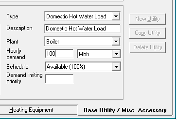
If a heated concrete slab will keep the ground beneath the rink from freezing, that must be modeled as well. This can be done using a hot-water base utility, as illustrated below.
Meet the C.D.S. Support Staff
ERIC BLECKINGER
Eric Bleckinger joined Trane as a marketing engineer in January 2011, after graduating with a mechanical engineering degree in 2010 from the University of Minnesota. Originally from St. Paul, MN, he spends the majority of his time enjoying the outdoors either running, golfing, or playing basketball.
If you had to live in a TV show for a month, which show would it be and why?
Any show on the Golf Channel, because by extension, I would have to be considerably better at golf.
If you could invite any three people (living or dead) to a dinner party, who would it be and why?
I’d probably only invite two guests, and let them choose the third. I would invite my grandfathers, who both passed before my first birthday. I’ve heard so many stories about those guys over the years, to finally get to know them for myself would be priceless.
CHARLIE JELEN
Charlie joined C.D.S. as a marketing engineer in November 2011 after working for three years as a sales engineer for a power transmission company in Minneapolis. He graduated with a mechanical engineering degree from the University of Minnesota in 2008. Charlie is a La Crosse native, and enjoys listening to music, riding his motorcycle, golfing, and snowboarding in his free time.
C.D.S. would like to extend congratulations to Charlie, who just got married this weekend. Best wishes!
What is your most prized possession?
My Harley-Davidson.
If you could invite any three people (living or dead) to a dinner party, who would it be and why?
Gregg Allman - Lead singer of my favorite band, The Allman Brothers. I’m sure he has some great stories.
William Harley – The original engineer for Harley-Davidson Motorcycles. I’d like to hear about the early days of the company.
Uncle Scott – My uncle died when I was really little. My family has told me my whole life that we look and act exactly alike. I’d like to meet him in general, but I’d also like to get an idea of what I might look like in 24 years.
Contributors: C.D.S. marketing engineers Eric Bleckinger, Charlie Jelen, and Chuck Stellberger.
C.D.S. Newsletter December 2012

