C.D.S. Newsletter March 2008
In this issue...
- How to Use ASHRAE Standard 62.1-2007 within TRACE™700
- Analyzing Geothermal Systems with TRACE
- Frequently Asked Questions
- Meet the Support Staff...Scott
How to Use ASHRAE Standard 62.1-2007 within TRACE™700
TRACE™ can be used to optimize ventilation airflow while meeting the requirements of ASHRAE Standard 62.1-2007. However before discussing how TRACE calculates the airflows, a basic understanding of ASHRAE 62.1 is helpful.
ASHRAE 62.1-2004 prescribed new minimum breathing zone ventilation rates and a new calculation procedure to find the minimum intake airflow needed for different ventilation systems. These new rates and procedures must be used to find the design or “worst-case” outdoor air intake flow, which establishes the required capacity of the mechanical system equipment [1].
With this understood the first step is to determine the minimum ventilation that the standard requires for each different space type. This is also known as the zone level procedure. The ventilation requirements for individual space types can be found in Table 6-1 of Standard 62.1. Once the minimum ventilation requirement for each space type is determined, equation 6-1 of the standard is used to calculate the required amount of airflow for the breathing zone. The effectiveness of the air mixture within the space, called the zone effectiveness, is determined based on the position of the supply diffusers and return-air grilles in each zone. This factor also accounts for any ventilation that would not be used within the breathing zone that could be re-circulated into the space. The zone-level procedure concludes with the solving of equation 6-2 to determine the required outdoor air for each zone. This is determined by dividing the Breathing Zone Outdoor Airflow by the Zone Effectiveness. This process must be completed for each zone that will comply with Standard 62.1.
Now that each zone-level ventilation requirement has been determined, the system-level ventilation can be calculated which is also known as the Outdoor Air Intake for the system. This procedure varies for different system types. For single-zone systems, equation 6-3 indicates that the ventilation requirement will be identical for both the zone and the system because they are one and the same. For 100 percent outdoor-air systems (also known as Dedicated Outdoor Air Systems within TRACE), equation 6-4 is used which sums the zone-level outdoor airflow to derive the system level. For multiple-zone, recirculating systems (i.e. variable-air-volume-reheat systems), sections 6.2.5.1 through 6.2.5.4 are used to determine the required system-level ventilation. Once the system level ventilation has been determined the procedure is complete.
Within TRACE, the procedure for applying Standard 62.1 is quite simple. The equations are processed in the background by the program in the same fashion that the procedure would be done with a spreadsheet or by hand. The next section will walk through the zone level procedure applied in TRACE and offer suggestions to ensure accurate zone level ventilation requirements are met per the standard.
To begin in TRACE, the zone-level ventilation requirements must be applied through templates or to the individual zone Airflows tab within Create Rooms. When starting a project, it is recommended to use templates to simplify and combine elements that will be applied to rooms or zones that share common characteristics. Using templates will vastly decrease the time it takes to enter the room parameters. The “Apply ASHRAE Std 62.1-2004” drop-down box should be changed to “Yes” to update the screen for Standard 62.1 airflow specifications. When this is done, the cooling- and heating-based ventilation components will be replaced with people- and area-based components. The Type drop-down box can then be utilized to change the space type which will assign the zone-level ventilation requirement directly from Table 6-1 in the Standard. Note that the TRACE library has been updated to reflect the Standard 62.1-2007 space type additions to Table 6-1, so there is no need to create the airflows manually. For zone-level design calculations, the people-based ventilation component is calculated based on the maximum quantity of people as determined in the cooling design definition of the people schedule. During hourly simulation, the people-based component can vary as the people schedule dictates.
In addition to the people- and area-based entries, the cooling and heating effectiveness values and recirculation fraction (seen in TRACE as Ez and Er factors) are entered on the same screen for the zone. Selecting the correct supply and return configuration for the cooling and heating airflows will automatically populate the predefined effectiveness factors. It is typically recommended that the recirculation fraction be determined based on the airside system selection by using the “default based upon system type” selection. The recirculation fraction only impacts systems that have secondary recirculation of return air such as parallel fan-powered systems. This fraction will account for the average system return rather than air recirculated for an individual zone.
At this point, only the minimum ventilation airflow requirement for each zone has been applied to the simulation and the system level implementation of Standard 62.1 is incomplete. At the system level, Standard 62.1 calculations must be enabled through Create Systems on the Advanced screen. This must be done for each system that will utilize Standard 62.1. The System ventilation flag should be changed from “Sum Room OA Reqs.” to the appropriate Standard 62.1 methodology. To comply with 62.1-2004 or 2007, one of the two 2004 methods must be applied. The user can choose between the traditional Standard 62.1 calculations or choose to include ventilation reset which will dynamically reset ventilation airflow as space conditions change throughout the simulation. Dynamic reset options include variations in zone occupancy (modeled in TRACE with occupancy schedules) and two versions of CO2-based, demand-controlled ventilation (DCV). When selecting the traditional version of Standard 62.1 without ventilation reset, the user can select Apply ASHRAE Std 62.1-2004 People Averaging, as dictated within Section 6.2.7 Dynamic Reset and discussed in Standard 62.1-2004 System Operation: Dynamic Reset Options (ASHRAE Journal Volume 48 no. 12). It is important to note that during the design calculations in TRACE, ventilation reset with or without demand-controlled ventilation cannot be modeled, because it is intended to model the worst-case scenario.
In addition, the Standard 62.1 Maximum Ventilation Z ratio can be set by the user. When entered, this number represents the maximum percentage of outside air within the conditioned supply air at minimum airflow conditions for each zone. This features's impact varies depending on whether the system is constant volume or variable volume. For variable-air-volume (VAV) systems, TRACE will calculate each zone’s outdoor-air fraction at minimum airflow conditions and determine if the calculated fraction exceeds the maximum Z fraction entered by the user. For any zone that exceeds the maximum fraction, TRACE will automatically increase that zone’s minimum stop on the VAV box so that the maximum Z-fraction limit is met. Fixing the maximum Z-ratio in variable-air-volume systems has the potential to increase reheat to prevent space overcooling. The lower the maximum outside-air fraction is set, the higher the risk for excessive zone reheat. In constant-volume systems, fixing the Z-ratio will simply oversupply the airflow to the space to meet the Z-fraction limit. Caution must be taken when using this fraction with constant-volume systems. The result may be over supplying airflow to the space that can lead to significantly increased fan-energy consumption and space control issues if the supply air temperature for the system has been fixed or limited.
Analyzing Geothermal System water loops using TRACE
Geothermal system designers face many unique challenges when creating an efficient and effective system. Perhaps the most critical is sizing the water loop for a ground source heat pump system. An undersized water loop may result in insufficient heat rejection or heat absorption, and ultimately an inability for the system to meet building load demands. Although TRACE is not a loop sizing program, several features provide insight into the proper design of a geothermal system. Details of setting up the basic ground source heat pump system can be found in the TRACE user’s manual and will not be discussed here. Rather, we will explore how TRACE can be used to aid in the analysis of the water loop for a geothermal system.
The first feature useful to sizing the water loop is calculated during the energy portion of TRACE. When ground source heat pump equipment is included with a TRACE calculation, a GT report is generated. This file can be found in the same location as the main file and although it will have the same name as the original file, the extension will be GT1 for alternative 1, GT2 for alternative 2, etc. This file contains the monthly peak heating and cooling loads calculated by TRACE and can be imported into GLHEPRO for use in calculating the capacity of the loop. The capacity of the loop from GLHEPRO can then be entered in the Thermal Storage Capacity field found in the Create Plants section, Cooling Equipment tab.
The next feature does not play a direct role in sizing the loop, but instead provides feedback regarding the loop’s defined capacity. When you build the ground source heat pump system in TRACE, you will notice a cooling tower and boiler are included as part of the default system. Although these components may not be used in reality, TRACE uses this equipment in the advent the water loop cannot reject/absorb sufficient heat to meet the defined condenser minimum and maximum temperatures. In other words, if the loop is sized to handle the entire heating and heat rejection loads, the condenser operation temperatures are correct, and the load profile is realistic, the modeled cooling tower and boiler may not operate. The Equipment Energy Consumption report will show if either of these components are used. If the backup tower or backup heat sources are showing consumption, increasing the capacity of the loop may help eliminate any use (assuming the other items listed above are accurate).
Note: Construction and climate play significant roles in determining a building’s load profile. These factors, coupled with limitations on loop size, may result in a scenario where the designed system will not satisfy the load requirements. In these situations, the addition of a cooling tower and/or boiler may be required. Before increasing loop size in TRACE, users must carefully consider such factors.
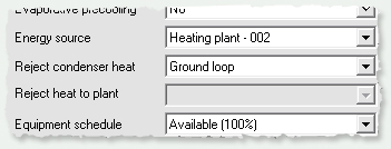
The final feature affecting the water loop deals with how TRACE models ground temperature if the condenser heat rejection type is input as “Ground loop.”
Since ground temperature will vary throughout the year and within the given location, TRACE utilizes the information contained within each weather location in conjunction with equations derived by the International Ground Source Heat Pump Association (IGSHPA), to determine a mean ground temperature for each month. TRACE applies each month’s mean ground temperature on an hourly basis and compares it against the leaving condenser temperature. The program then determines the appropriate heat pump energy use.
TRACE offers designers many features to achieve successful integration of their ground source design into the building’s HVAC plan. The combination of TRACE’s default ground source heat pump equipment, the ability to export load information to GLHEPRO, and the calculation power of the program provide users with the tools necessary for designing a successful system. As a final note, TRACE models other “groundwater source” systems such as those which utilize river or lake water.
By Michael Patterson, Marketing Engineer, C.D.S.
Trane C.D.S. Support.
For more assistance with Standard 62.1 in TRACE, contact the CDS Support Center at 608-787-3926 or email cdshelp@trane.com.
In TRACE, why do I have oversizing and undersizing in my checksums report?
The over/undersizing which appears on the Checksums reports, typically occurs with constant-volume system types, especially Single Zone, Fan Coil, Variable Temperature Constant Volume and Multizone Systems. This value is an actual load on the coil that cannot be ignored. The TRACE 700 Users Manual, pp 6-51 provides several examples for calculating over/undersizing and explains why it occurs and how to minimize it. An electronic version is also installed in the Documentation directory where TRACE is installed. Click here to download in-depth information.
Why archive a file?
Archiving creates smaller file sizes which makes projects more portable for e-mailing or transferring between computers. In addition, when the archive option is selected the program will collect all associated information including the custom library members.
TRACE compresses the file and creates a .taf (TRACE Archive File) file extension. This ensures that the custom library members that were created for the project stay with the file.
In the Rooms tab of Create Rooms within TRACE, what is the difference between Thermostat Schedules and the Thermostat Driftpoints, and how do they interact?
The thermostat driftpoints are temperatures that the room is allowed to drift up or down to during periods of low or no occupancy. If the room temperature drifts outside of these set temperatures the cooling or heating coils will be activated (assuming the coils are available to operate). TRACE 700 allows the room to drift up or down to the driftpoint temperatures during hours in which the people schedule for the room is 5 percent or less. If the people schedule reads greater than 5 percent, the cooling thermostat will try to control the room to the design setpoints.
The Thermostat schedules allow the user to enter heating and cooling setpoints based on the time instead of occupancy. Thermostat schedules are created using the Library/Templates Editors program.
Note: If a cooling-thermostat schedule is selected (other than the default None), the program will ignore the entered cooling setpoints and driftpoints for the energy simulation. However, the setpoints will be used during the design calculations. The heating-thermostat schedules and driftpoints work identically.
Scott Hintz
Scott joined Trane in July 2007 after spending eight years with Siemens Building Technologies. He earned his B.S. in Industrial Engineering from the Milwaukee School of Engineering. At Siemens, Scott held various positions including Applications Engineer and Project Manager for Room Level Automation Controls. He was nominated five times for Engineering and Technical Achievement Awards and won in the Innovation category for a Fume Hood control scheme. Scott was also project manager for Siemen's Venturi air valve development and Siemens automated terminal box commissioning tool. In addition to his support role as a C.D.S. Marketing Engineer, Scott is responsible for project management of maintenance of existing and development of new software.
Q. What three items would you want if stranded on a desert island?
A. A wind up LED flashlight, my softball glove (in case a game broke out), and whatever gum MacGyver chewed because apparently it could work as a plastic explosive and was strong enough to hold the wing of a 747 together.
Q. What is your favorite C.D.S. support question?
A. “Do you live on a farm?” ... after I stated C.D.S. is located in La Crosse, Wisconsin.
C.D.S. Newsletter May 2008

