C.D.S. Newsletter April 2009
In this issue...
- New Feature in TRACE 700 Helps Resolve Errors
- Chilled-Beam and Displacement Ventilation Systems in TRACE 700 Version 6.2.1
- Save Time with Available Resources
- Meet the C.D.S. Support Staff...Mike Patterson
- Frequently Asked Questions: TOPSS, TAP
New “Scan for Errors” Feature Available in TRACE 700
A new feature is available in TRACE 700 that automatically scans a file for common errors during the calculation process. Scan for Errors is a troubleshooting feature that can also be run manually by clicking the Scan for Errors button on the Calculate and View Results screen.
If any errors are found, they are displayed on an error log. More specific information about the error(s) can be accessed by clicking the View Details button on the screen. The error log may also be opened in Notepad by clicking the View in Notepad option, enabling the user to edit the file while continuing to view the errors report.
Some examples of common errors include the following:
- Systems that have improperly designed optimum start schedules
- Zone-level systems that do not have room thermostats
- Systems that do not have humidistats but include direct dehumidification
- Rooms that do not have CO2 sensors but the systems include demand controlled ventilation based on CO2
- Room ventilation schedules that do not match when the rooms share a single set of outside air dampers
- Improperly defined wall and roof materials that do not include outside/inside film resistances
- Systems that have the return air path defined as a plenum but the plenum has been zeroed out in the assigned rooms
- Static pressures missing for fan types defined in Create Systems
- Custom library information is missing and the file cannot be calculated
- Missing ASHRAE Design weather information for custom weather locations
- Design supply air dry bulb temperatures that exceed supply air temperature reset inputs
For more information about this feature, refer to the online help file in TRACE 700.
Chilled-Beam and Displacement Ventilation System Types Available in TRACE 700
Chilled beams and displacement ventilation can now be modeled in TRACE 700 (version 6.2.1). TRACE is one of a very limited number of domestic applications to model these system types. The true performance of these systems can now be verified as opposed to using potentially inaccurate hand calculations.
TRACE offers two chilled-beam strategies: passive and active. Each chilled beam system can be configured to a particular building scenario.
Five configurations of displacement ventilation systems are available. The displacement ventilation systems include both constant and variable volume systems, as well as systems that include auxiliary forms of cooling such as chilled beams or ceiling panels.
Both systems include the ability to modify and configure the auxiliary heating and cooling coils such that a wall convector could be replaced by a fan coil. In addition, the auxiliary system fan control can be defined, as well as the supply path for the primary air, underfloor plenum height, and percentage of sensible gains to the occupied layer.
For more information about these systems, including sample scenarios, refer to the updated TRACE 700 User’s Manual. To access the manual from the menu bar in TRACE, select Help > Documentation > User’s Manual.
Read about all the new features in TRACE update 6.2.1.
Resolve Questions Quickly with Support Resources
Perhaps the best-known benefit of maintaining a TRACE 700 license is access to our support center. Whether you send an e-mail or call in, the support center offers you solutions to whatever issue you may be experiencing. However, three other resources are available to licensed users: the Getting Started manual, the TRACE 700 User’s Manual, and the Knowledge Base. These resources may contain the answers you need.
The Getting Started Manual is particularly beneficial for new users or those who have not used the program in a while and want a quick refresher. Broken down into the various phases of the program (Load/Design, Airside Systems, Plants, and Economics), the manual walks you through the creation of a fictitious school. Throughout the process, you will learn how to navigate the program and perform basic functions. A completed tutorial file providing the “approved” solution is included.
For more advanced users, the TRACE 700 User’s Manual provides more than 400 pages of information on how to model specific scenarios. The first two sections include basic information and an overview of the program phases. The remaining sections delve into detailed aspects of how to model different applications. For example, how to model various chiller plant arrangements, cogeneration, free-cooling, air-to-air energy recovery, dedicated outdoor air units, and ASHRAE Standard 62.1 are just a few of the many items covered in this manual. A modeling guide for LEED® is also included, as well as a section on common modeling mistakes. This is an invaluable resource in which you can find answers to many of your questions.
Electronic versions of both manuals can be accessed from TRACE. Open the Help menu, click Documentation, and then click the appropriate manual. Printed books are available to order for $100 from C.D.S. email us at CDSadmin@trane.com or call 608.787.3936.
If you cannot find the answer to your question in either manual, access our Knowledge Base on www.tranecds.com. The recently updated Knowledge Base contains the frequently asked questions we see in the support center. Simply select the program you have a question about and choose from the list of topics. This is a great place to go if you cannot find the answer in the User’s Manual and before trying the support center.
These resources were developed for licensed users and offer a wealth of information to quickly answer common application questions. Our support center is always available, but you may be able to save time by utilizing one of these resources first—take time to review them today!
Meet the C.D.S. Support Staff...Mike Patterson
Mike joined Trane in May 2007 as a marketing engineer with C.D.S. He is a graduate of the United States Air Force Academy with a bachelor’s degree in Engineering Mechanics. He earned his MBA from Regis University. In his current role, Mike supports customers with many Trane software programs including TRACE 700, System Analyzer, and Engineering Toolbox. Mike grew up outside Fort Worth, Texas and enjoys spending time with his wife and daughter.
Q. What three items would you want if stranded on a desert island?
My wife and daughter plus these 3 things...
A good book (as opposed to a bad one).
A healthy supply of coffee.
A satellite TV so I can watch Texas beat Oklahoma in football!
What is the most enlightening book you've read in the past year?
Team of Rivals: The Political Genius of Abraham Lincoln, by Doris Kearns Goodwin
Frequently Asked Support Questions
Why am I getting an expiration message when I launch TOPSS?
Due to AHRI requests as well as a continuous effort to provide customers with the most current information, Trane has implemented a new version control process for TOPSS. TOPSS customers are currently required to update software to ensure they are using the most current Trane product selections. Trane continuously strives to improve product and this new version control process will ensure consistency and accuracy. In addition, the TOPSS team is working on improving the download process.
The current version of TOPSS is 8.6.036. The following are install/update instructions:
Before downloading we suggest that you uninstall the current version of the program using the following steps.
1. If you want to save previous selections, copy the job files with .psd extensions to another location outside of the \TOPSS folder.
2. Uninstall TOPSS by choosing the Start > Settings > Control Panel > Add or Remove Programs. Select TOPSS and Remove it.
3. Go into Windows Explorer and delete the \TOPSS folder.
4. Choose Start > Search > For Files or Folders. Search for the TOPSS.ini file and delete it.
To download TOPSS:
Customers who would like to download and install a copy of TOPSS version 8.6.036, click here.
Please note that Windows 2000 or newer is required. The user will need temporary administration rights to their computer during the installation process.
Select TOPSS 8.6.036 Full Version
Enter your customer ID when prompted(your customer ID is a three character number preceded by #).
Click Save to copy the update to your local hard drive. (Hint: Saving the file on your desktop will make it easy to find.) Download time will vary depending on your connection.
Once the file download is complete, double click on the .exe to install the application.
Remember to uninstall prior to downloading the update.
If you have any questions feel free to contact C.D.S. Support .
What is the correct way to model breakout or radiated noise in a duct passing through a room in Trane Acoustics Program (TAP)?
How do I model sound in the room?
The sound radiated from a duct passing through or above the ceiling tile of a room is modeled using the duct breakout element in TAP. The duct breakout element (elements, sound transmission, duct breakout/in) calculates how much of the sound inside the duct passes through the duct wall to the area surrounding the duct.
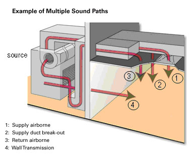
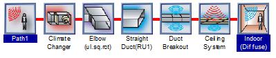
The duct breakout sound element is only used in a duct breakout sound path (see figure above). A duct breakout sound path contains all the elements required to model the sound traveling from the sound source to the portion of the ductwork that is over the room where duct breakout is a concern. After the duct breakout element, the sound path then continues outside the duct. For example, if the duct is in a ceiling plenum the next element would be a ceiling transmission loss element to account for the transmission loss of sound traveling through the ceiling and into the room.
Once in the room, an indoor receiver sound correction element is used to account for the acoustical character of the room. Choose the Diffuse Field Theory from the Room Equation box (Elements>Receiver Sound Correction>Indoor). As the description notes, this equation is used for sound from a line source. Both the duct breakout element and Diffuse Field Theory elements ask for the length of the duct. This is the length of the duct over the room (or area) of concern.
If the duct is wrapped with a special material to increase transmission loss (e.g., a weighted vinyl or gypsum board) use a duct lagging element (elements, duct sound attenuators, lagging) in addition to, and directly after, the duct breakout element to model the added material.
An example file is installed with TAP. A documented example can be found in the TAP "Getting Started User's Manual" as well.
What are the limitations of the TAP trial software on Trane.com?
The demo is set up to model a maximum of two paths and seven items per path. The licensed version offers unlimited number of paths and items per path. The output in the demo can be viewed but not printed.
Download the TAP trial software.
C.D.S. Newsletter August 2009

