C.D.S. Newsletter September 2011
In this issue ...
- TRACE 700 Version 6.2.7 Available
- Modeling Thermal Energy Storage in TRACE 700
- New Courses Available for LEED Credential Maintenance
- Frequently Asked Support Questions
TRACE 700 Version 6.2.7 Available
Download update
TRACE 700, Load Design, Load Express, and Chiller Plant Analyzer updates are now available. The newest version, 6.2.7, includes the following updates:
- Environmental impact information updated to the latest eGRID values
- New Geothermal library to import vertical bore sizing calculations
- New FlexEnergy microturbine library members added to the Cogeneration library
- Updated 90.1-04 and 90.1-07 library members
For a complete list of changes to this version, visit the TRACE 700 Version Information section.
Modeling Thermal Energy Storage in TRACE™ 700
In areas where the local utility company offers incentives in the form of rate structures or rebates, adding thermal energy storage to an HVAC system can reduce energy costs associated with comfort cooling by shifting equipment operation from high- to low-cost times of day.
Ice tanks are often used as a means of thermal storage because of their compact size and pre-engineered design. During off-peak periods (when utility rates are low), the chiller cools a glycol-water mixture to a temperature below the freezing point of water. This mixture then circulates through tubes within the ice tank, where it freezes the surrounding water. When cooling is needed during an on-peak period (when utility rates are high), the glycol-water mixture—heated by the building load—circulates through the storage tanks to melt the ice.
When modeling thermal energy storage in TRACE, pay special attention to the following:
Equipment tank charging capacity and efficiency
Thermal storage adds another mode of operation for the chiller(s): charging the ice tanks. Define this second mode of operation in TRACE 700 on the Cooling Equipment tab of Create Plants. Enter a tank charging capacity and energy rate for each piece of equipment that generates ice.
When the piece of equipment is in tank charging mode (according to the schedule, which is covered below), TRACE will use its tank charging capacity and energy rate to calculate energy consumption.
Equipment and thermal storage schedules
In order for TRACE 700 to know when a piece of equipment will make ice, both the equipment and thermal storage schedules must be assigned. To assign the equipment schedule, click the Controls button on the Cooling Equipment tab of Create Plants. Under Equipment schedule, select Available for Thermal Storage. This schedule must be assigned to each piece of equipment individually; it forces the ice-making chiller(s) to follow the schedule selected for thermal storage.
Assign the Thermal Storage schedule to the thermal storage device. It is created in the Schedule Library and defines if the thermal storage device is storing energy (Charging), releasing energy (Discharging), helping meet the building load along with the chillers (Satisfy load), allowing the chillers to meet the building load by themselves (SatNoTank) or if they are off completely (Off). It is important to define the correct schedule for your application since there are different ice-making strategies.
Custom thermal storage and equipment library members
The operation of storage devices and equipment in thermal storage applications is very job specific. For this reason, it is important to correctly define the unloading and control strategies for these devices. In TRACE 700, this can be done in the Cooling Equipment and Thermal Storage libraries. For chillers, it is best to have performed a selection of the units at both their design conditions (regular operating temperatures and ice-making temperatures). This will allow you to define the unloading curves for both operating modes.
In the Thermal Storage library, the charging strategies, discharging strategies, fluid properties, and losses can be defined.
Additional resources
- Thermal Storage Engineered Systems Clinics (Trane literature numbers ISS-CLC-1, ISS-CLC-2, ISS-CLC-3, and ISS-CLC-4)
- Control of Ice Storage Systems (Applications Engineering manual, Trane literature number ICS-AM-4)
- Ice Storage Systems (Applications Engineering manual, Trane literature number SYS-AM-10)
New Courses Available for LEED Credential Maintenance
New on-demand courses have recently been added to the Trane.com Continuing Education offering, including courses that qualify for 1.5 LEED-specific continuing education (CE) hours from the U.S. Green Building Council (USGBC). As part of USGBC’s credential maintenance program, LEED APs are required to earn 30 CE hours biennially, 6 of which must be LEED-specific. View the course offerings at www.trane.com/continuingeducation.
Course Spotlight: High-Performance VAV Systems
This course will discuss design and control strategies that can significantly reduce energy use and ensure proper ventilation in VAV systems. Topics include ventilation system design and control, optimized VAV system controls, cold air distribution, and other energy‐saving strategies.
How do I model hot gas reheat for dehumidification?
Hot gas reheat uses a refrigerant piping configuration that places a reheat coil downstream of the cooling coil, where hot refrigerant warms the supply air. This allows a portion of the refrigerant cycle's rejected heat to be reclaimed as reheat.
To model hot gas reheat for dehumidification in TRACE, complete the following steps. Note: This scheme is available for unitary cooling equipment, including air-cooled unitary, water-cooled unitary, and water source heat pumps. This feature assumes that the associated airside system has a reheat coil located downstream of the cooling coil for dehumidification reheat purposes.
1. Define a form of dehumidification within the Temperature/Humidity tab of Create Systems.
2. Open the Create Plants screen and click the Cooling Equipment tab. Click Controls. The Cooling Equipment Controls screen displays.
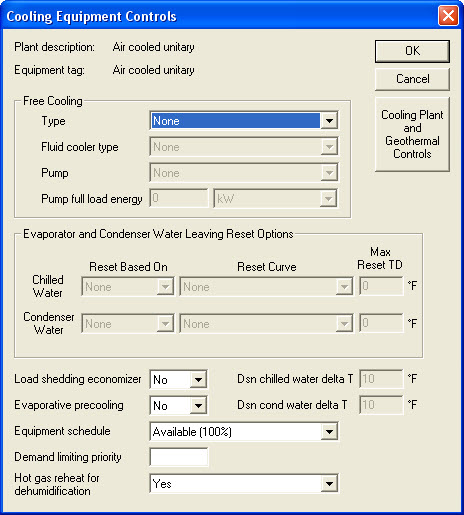
3. In the Hot Gas Reheat for Dehumidification field, select Yes.
4. Click OK.
How do I model an air-to-air heat pump?
The following example describes how to model an air-to-air heat pump with supplementary electric-resistance heat as a backup.
1. In Create Systems, create an airside system and define it as an "Incremental Heat Pump".
2. In Create Plants, use air-cooled unitary and electric resistance plants to begin defining the heating and cooling plants. Rename the cooling plant "Heat Pump" and the heating plant "Electric Resistance".
3. With the cooling plant displayed on the Cooling Equipment tab, select Air to Air Heat Pump from the drop-down list in the Equipment Type field.
Note: In the Library/Template Editor verify that the design parameters of the standard TRACE library meet your equipment design characteristics.
4. In the Backup Heat Source field, select the electric resistance heating plant. This will serve as a backup if the heat pump cannot satisfy the heating load.
5. In the Reject Condenser Heat field, select Heat Rejection Equipment.
6. Click on the Heating Equipment tab to define the heating plant.
7. From the drop-down list in the Equipment Type field, select one of the electric resistance heat options.
8. In Assign Systems to Plants, assign each coil load to the appropriate plant.
The TRACE User's Manual excerpt covers this procedure in more detail.
C.D.S. Newsletter December 2011

